FREE ALLISON DOC Software: Data Bus Traffic View on ALLISON Transmission
Data Bus Traffic View
 |
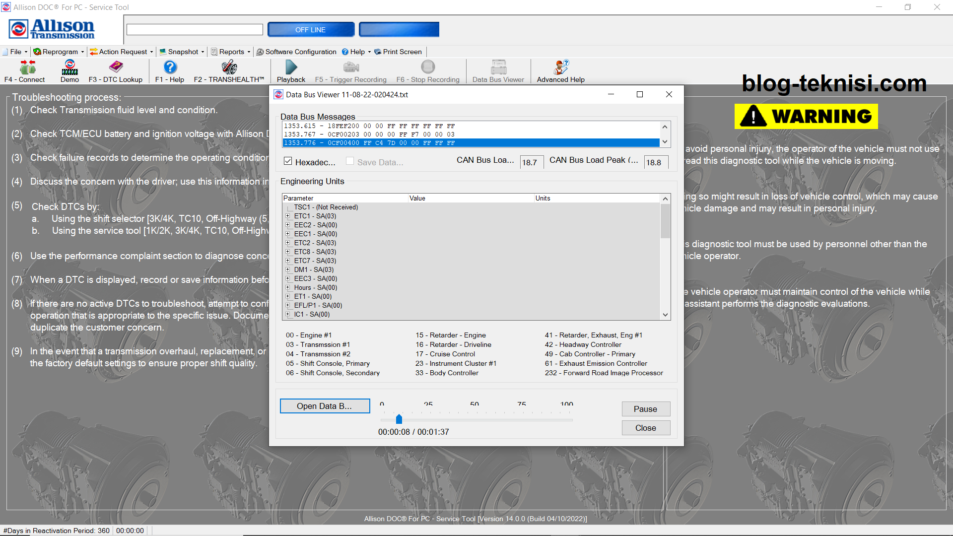
| Figure 1.1 - Data Bus Viewer (Active) |
The real-time data flowing on the vehicle's data bus (CAN, J1939, J1708, J1850, GMLAN, or proprietary CEC1 protocol) is viewable in the Data Bus Traffic Viewer. It's presents the data link stream data in raw format and, when available some J1939 TCM Received/Broadcasted messages in engineering units.
The following table contains all the data communication protocols that, depending upon its availability at the diagnostic connector, could be used to connect Allison DOC and to monitor data with the Data Bus Viewer in either active or passive mode.

The Data Bus Viewer has the following sections (as Figure 1.1 above):
#Data Bus Messages
This sections displays the numeric representation of every message that is going through the selected communication link. The data is displayed in decimal (base 10) or hexadecimal (base 16) number systems. The decimal numeric system can be activated with the hexadecimal check box.
CAN statistics information appear when these statistics are available from supported adapters. Not all adapters support this functionality.
- CAN Bus Load (%) - displays current percent CAN bus load.
- CAN Bus Load Peak (%) - displays the peak percent CAN bus load since the data bus viewer was opened.
#Engineering Units
Engineering Units (only available when connected via J1939) includes every SAE J1939 Message and Parameter supported by the Allison Transmission controller. This information consists of all Messages and Parameters the transmission control module broadcasts and receives via J1939.
- Parameter - displays SAE J1939 Messages the TCM can receive/send. Each SAE J1939 can be expanded to display the corresponding SAE J1939 parameter.
- Value - the value/state of the parameter.
- Units - the units of measure used for the value.
Source Addresses - Describes all Source Address (SA) that can be included/displayed in the Data Bus viewer.
MID/SA - (J1708 or J1850 only) Message Identifier/Source Addresses code - the message type/source/destination.
Component ID - (J1708 or J1850 only) Manufacturer of a controller.
Model - (J1708 or J1850 only) A controller's model number.
Software ID - (J1708 or J1850 only) Identifies the software used by the controller.
#Command Button:
- Pause - pauses and continues the Data Bus Message display.
- Clear - clear all Data Bus Message data.
- Save - displays the "File Save" dialog box and automatically save the last 2 minutes of data displayed on the Data Bus Viewer, under the entered file name or under a default file named, defined by date and time. If the "Save Data Continuously" check box is selected, the tool will continuously save data (as opposed to the last 2 minutes of data), until the user clicks on the "Save" button.
To find the recorded file, use Windows Explorer and navigate to the user data directory of Allison DOC (usually default to...... \Documents and Settings\All Users\Documents\Allison Transmission\Allison DOC for PC - Service Tool), then open the Saved Data Bus Viewer Files folder. The raw data can be viewed with Notepad or WordPad. Also, the user can playback these file using the Data Bus Viewer feature in the service tool.
- Close - closes the Data Bus Viewer window
#Displaying the Data Bus Viewer
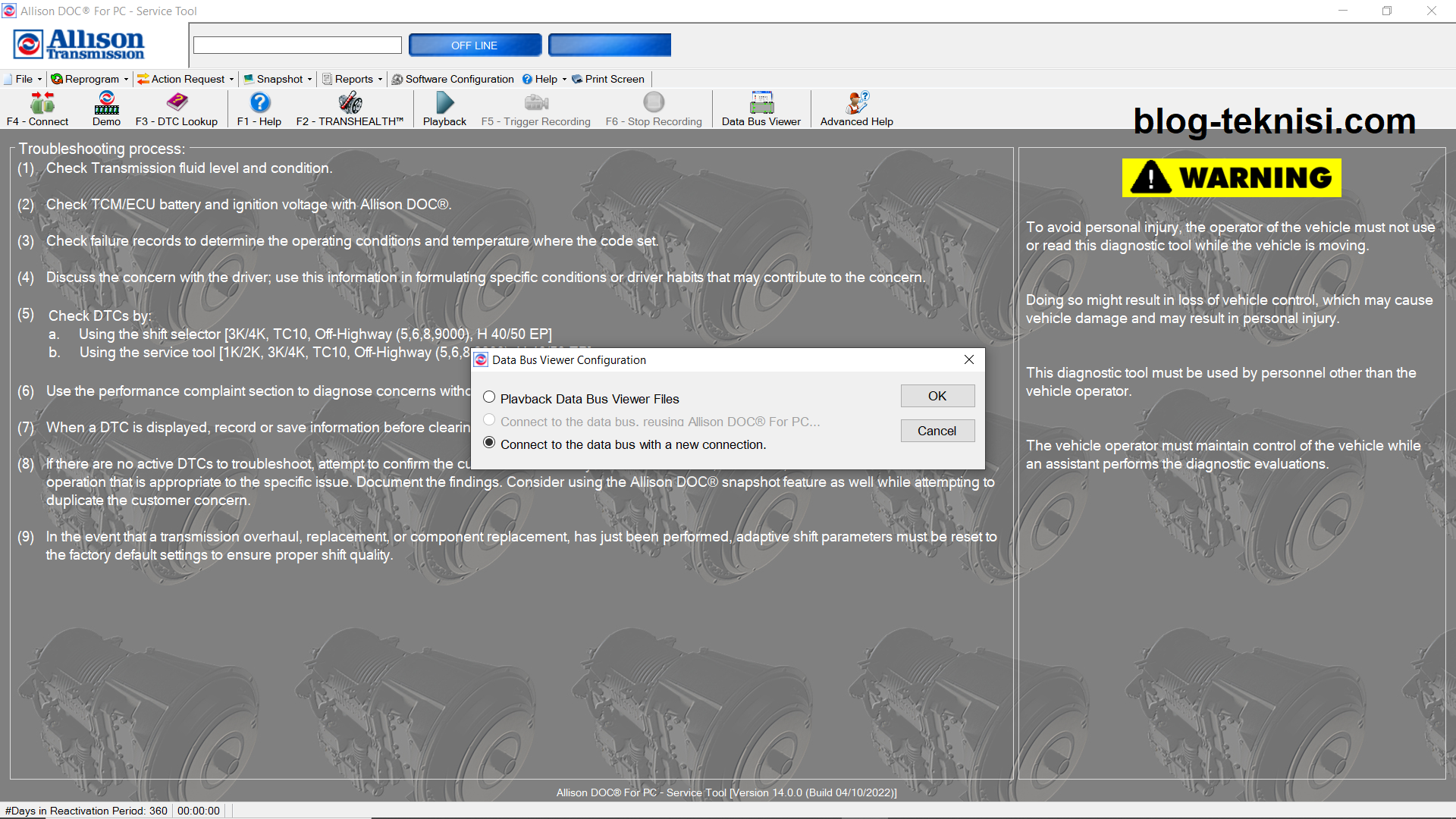
1). Select Data Bus Viewer or Transmission Connect/Disconnect from the dialog box, the Data Bus Viewer Configuration window displays.
 |
| Figure 1.2 - Data Bus Viewer |
2). Select Connect to the data bus with a new connection option and click OK. The Communication Adapter Setup window displays.
 |
| Figure 1.3 - Data Bus Viewer Configuration (1) |
3). Select your Adapter: Vendor, Protocol, and Device for a particular translator device, then click OK.
 |
| Figure 1.4 - Communications Adapter Setup |
4). The Data Bus Viewer is displayed. This function captures all the data being sent through the communication link (as Figure 1.1).
 |
| Figure 1.5 - Data Bus Messages |
 |
| Figure 1.6 - Save As (Data Bus Viewer) |
#Playing Back Data Bus Viewer Files
1). Select Data Bus Viewer from the file menu, or the Transmission Connect/Disconnect dialog box. The Data Bus Configuration window displays.
 |
| Figure 1.7 - Data Bus Viewer Configuration (2) |
2). Select Playback Data Bus Viewer Files and click OK. The Data Bus Viewer window displays.
 |
| Figure 1.8 - Open Data Bus Session |
3). Click on the Open Data Bus Session, and select the file you want to playback, then click Open.
 |
| Figure 1.9 - Data Bus Viewer (Playback) |
Read More:
Blog.Teknisi
you have CAN record the traffic Allison transmission for L5P duramax?
ReplyDelete