SPN 441 - FMI 3 (Diagnostic Code: Auxiliary Temperature Sensor - Voltage Above Normal)
AUX Temp (Auxiliary Temperature) - SPN441 FMI3 (1836-3)
AUX Temp Sensor is optional equipment, with CAT P/N 370-3830.
→Additional installed for the Hazardous Location.
→Installed on Explosion Protection Engine Kit (such as Pyroban) at Exhaust Manifold System.
 |
| Figure 1.1 - SPN 441 FMI 3 (Murphy PowerView) |
#Auxiliary Temperature Sensor Installation Status
Program Auxiliary Temperature Sensor Installation Status to Installed if an Auxiliary Temperature Sensor is installed. This will allow the display for the Engine Monitoring System (EMS) to monitor the temperature of another system. Otherwise program this parameter to Not Installed.
→Accessing Configuration - General Information on CAT ET.
 |
| Figure 1.2 - Auxiliary Temperature Sensor (Installed) |
#Troubleshooting
The troubleshooting procedures for the Diagnostic Codes of each temperature sensor are identical. The temperature sensors are passive sensors that have two terminals. The temperature sensors do not require supply voltage from the Electronic Control Module (ECM).
#Pull-up Voltage
The ECM continuously outputs a Pull-up voltage on the circuit for the sensor signal wire. The ECM uses this Pull-up voltage in order to detect an open in the signal circuit. When the ECM detects the presence of a voltage that is above a threshold on the signal wire, the ECM will generate a -03 Diagnostic Code. If the sensor is disconnected at the sensor connector, the presence of Pull-up voltage at the sensor connector indicates that the signal wire and the return wire from the sensor connector to the ECM are good. If the sensor is disconnected at the sensor connector, the absence of Pull-up voltage at the sensor connector indicates an open in the signal wire, an open in the return wire, or a short to ground. If the sensor is disconnected at the sensor connector and the voltage on the signal wire at the sensor connector is different from Pull-up voltage, the signal wire is shorted to another wire in the harness. Read More: Pull-up Voltage and How ECM Uses it to Determine Diagnostic Conditions.
Test Step 1. Inspect Electrical Connectors and Wiring
A. Turn the keyswitch to the OFF position.
B. Thoroughly inspect ECM connector and the connectors for sensor.
C. Perform a 45 N (10 lb) pull test on each of the wires in the sensor connector and the ECM connector that are associated with the Active Diagnostic Code.
D. Verify that the latch tab of the connector is properly latched.
E. Check the allen head screw on the ECM connectors for the proper torque.
F. Check the harness and wiring for abrasions and for pinch points from the sensor to the ECM.
Expected Results: All connectors, pins, and sockets are completely coupled and/or inserted. The harness and wiring are free of corrosion, of abrasion, and of pinch points.
Test Step 2. Check for Active Diagnostic Codes
A. Connect Caterpillar Electronic Technician (ET) to the Service Tool connector. Read More: How to Connecting Caterpillar ET Software to the ECM.
B. Turn the keyswitch to the ON position.
C. Check for Active Diagnostic Codes on CAT ET. Record any Active Diagnostic Codes. Wait at least 15 seconds in order for the Diagnostic Codes to become active.
Results: An open circuit Diagnostic Code -03 (SPN 441 - FMI 3) is active at this time (refer to Figure 1.1 above).
 |
| Figure 1.3 - Auxiliary Temperature (1836-3) |
Test Step 3. Check the Pull-up Voltage at the Sensor Connector
A. Disconnect the suspect sensor at the sensor connector.
B. Turn the keyswitch to the ON position.
C. Measure the voltage between terminal 1 (sensor signal) and terminal 2 (sensor return) at the sensor connector.
D. Turn the keyswitch to the OFF position.
Expected Results: The voltage is 5.5 ± 0.5 Vdc.
Test Step 4. Create a Short at the Suspect Sensor Connector
A. Turn the keyswitch to the OFF position.
B. Install a jumper wire between terminal 1 and terminal 2 on the connector for the suspect sensor. Connect the jumper on the harness side of the connector.
C. Turn the keyswitch to the ON position.
 |
| Figure 1.4 - SPN 441 FMI 4 (Murphy PowerView) |
D. Check for Active Diagnostic Codes on CAT ET. Record any Active Diagnostic Codes. Wait at least 15 seconds for activation of the short circuit Diagnostic Code -04 (SPN 441 - FMI 4).
 |
| Figure 1.5 - Auxiliary Temperature (1836-4) |
E. Remove the jumper wire.
F. Turn the keyswitch to the OFF position.
#Trip points for the Monitoring System
The Monitoring System determines the level of action that is taken by the Electronic Control Module (ECM) in response to a condition that can damage the Engine. When any of these conditions occur, the appropriate Event Code will trip (SPN 441 - FMI 15/ SPN 441 - FMI 0).
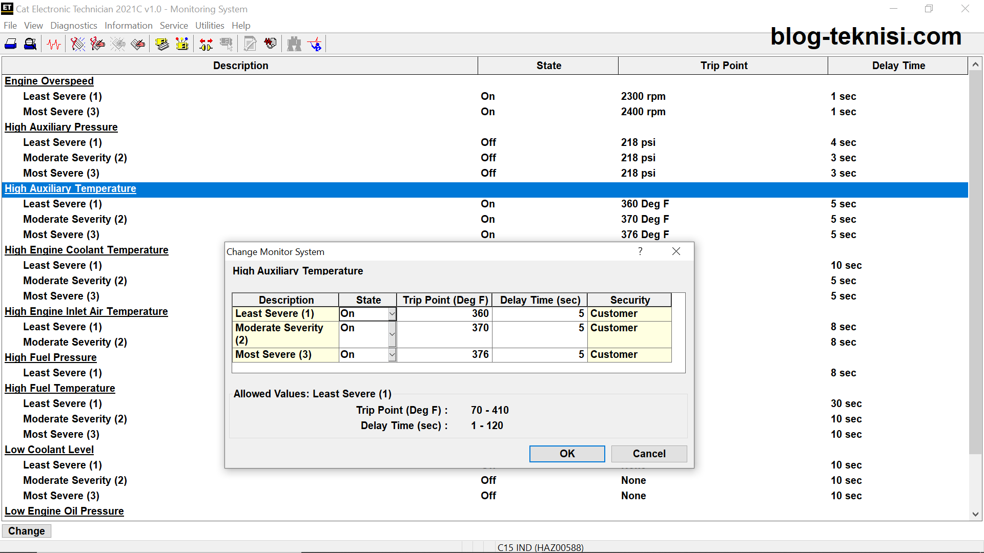 |
| Figure 1.6 - High Auxiliary Temperature |
Note: Please keeps monitoring on Exhaust Back Pressure through manual gauge, or Auxiliary Pressure Sensor (if equipped), when you set disabled/ Not Installed this optional setting.
 |
| Figure 1.7 - Exhaust Back Pressure |
Blog.Teknisi
TOP PICKS - GLOBAL ELECTRONIC INDUSTRY LEADERS
ReplyDelete