Senders/ Sensors on Electronic Engines
Senders/ Sensors (Caterpillar)
 |
| Senders/ Sensors (Variable Input Devices) |
Read More:
Identify Types of Basic Circuit Faults and Wiring Harness Test
PULL-UP Voltage and How the ECM Uses it to Determine Diagnostic Conditions
Senders/ Sensors (variable input devices) can be classified in several ways as illustrated in the chart above. This chart shows the typical sensors and senders found on Electronic Engines and Machines.
The types of senders and sensors in this chart are classified by the parameter monitored. Other sensor characteristics include:
- Sensor Makeup: Internal components that determine the type of signal produced.
- Active or Passive: An active sensor receives power from the ECU or battery and must be powered to check operation. A passive sensor does not require power from the ECU and can be tested without power applied.
- DMM Measurements: Type of electronic signals for a sensor that a digital multimeter can measure.
#Passive Sensors
Passive sensors are typically two-wire sensors, with the exception of single-wire senders. Passive sensors do not require ECU or battery power in order to function and test. Testing can usually be accomplished by checking the resistance of the sensor. All passive sensors will be of the analog type.
-Pin assignments for passive sensors are as follows:
• Position 1: Signal
• Position 2: Return/Ground
#Active Sensors
Active sensors are typically three-wire sensors, but can be two- or four-wire. Active sensors require ECU or battery power in order to function and test. Active sensors fall into one of two categories:
- Analog: A signal that varies smoothly over time and in proportion to the measured parameter. These signals are typically DC voltage.
- Digital: Digital signals are usually associated with computerized electronic controls and measuring devices. The signal(s) will switch between two distinct levels, such as 0 to +10 Volts, or more simply stated as low and high. The internal electronics of a sensor determine the amplitude or level.
• A or 1 position: Power
• B or 2 position: Return/Ground
• C or 3 and 4 position: Signal
#Analog Signals
As previously mentioned, an analog signal is a signal that varies smoothly over time and in proportion to the measured parameter. Analog signals on Electronic Engines are typically AC or DC voltage.

The above illustration shows a DC analog signal trace of a pressure sensor. This type of electronic signal is proportional to the amount of pressure sensed in a system. As pressure increases, the resistance of the sensing device changes. The change in resistance, and thereby voltage, would be sensed by the ECU. NOTE: Analog sensors that have a DC output will have a typical operating range of 0.2 volts to 4.8 volts. Voltage ranges may be different, depending on application.

The above illustration depicts a single wave produced by analog speed/timing sensors. Sine waves are types of signals that changes direction (AC). In the above example, the voltage rises to a peak positive value, drops to zero, reverses polarity, rises to a peak negative, and returns to zero. One positive and one negative alternation produces one cycle, the cycle is repeated continuously.
The number of cycles that occur in one second is called frequency, expressed in Hertz (Hz). As the speed of the measured parameter increases, so will be the frequency.
#Digital Signals
As previously stated, digital signals switch between two distinct levels such as 0 to +10 Volts, or more simply stated as high and low. The internal electronics of a specific device determine the amplitude or level. Digital signals on Electronic Engines are typically of the Hall-Effect or pulse width modulated (PWM) type.

The above illustration depicts a typical Hall-Effect signal. Hall-Effect sensors operate using a current field and a piece of iron (gear tooth). When the gear tooth is introduced perpendicular to the current field, all of the electrons are forced to one side of the semiconductor (remember—like forces repel and opposites attract). When current is forced to one side of a semiconductor, a difference in potential
(differential voltage change) can be detected. The gear tooth moving across the Hall cell gives a “high” state. The “low” state indicates the Hall cell is located in the valley between two teeth.
Digital signals created by Hall-Effect will have a frequency that varies with the speed of the parameter being measured, and will typically have a constant duty cycle of 50%.
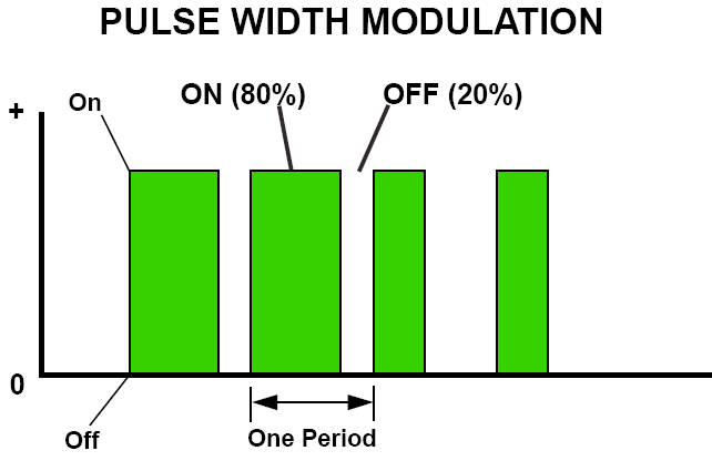
The above illustration above shows a PWM signal. A PWM signal is measured in duty cycle, which is defined as % time on (high) vs % on time off (low) for one pulse. In the example above, the signal is on (or high) for 80% of the pulse and off (or low) for 20% or the pulse. This would indicate a duty cycle of 80%.
On Electronic Engines, a position sensor would be good example of a device that produces a PWM signal. A PWM signal has a constant frequency output and the duty cycle (% of time vs time off) of the signal varies as conditions (rotary position) change. The output of the sensor is sent to an ECU where the signal is processed.
Blog.Teknisi
This is a great article with lots of informative resources. I appreciate your work this is really helpful for emergency exit light testing to everyone. Keep continue.
ReplyDeleteThis site is the best you have information and data which is simple to understand.thank you.keep it up
ReplyDeleteThis blog is completely informative and productive in nature. All the things mentioned about industrial automation are true.
ReplyDeleteI am heartily thankful to you that you have shared this best information with us. I got some different kind of knowledge from your web page, and it is really helpful for everyone. Thanks once again for share it. swaraj 735 xt
ReplyDeleteWow, your post is really very useful thanks for sharing about WANROY Batterie. It's really informative. keep sharing more with us.
ReplyDeleteGreat post by the great author, it is very massive and informative about Online Visitor Management System but still preaches the way to sounds like that it has some beautiful thoughts described so I really appreciate this post .
ReplyDeleteA well-designed engine ensures a smooth ride. 350 crate engine
ReplyDeleteStrong foundation for power generation. yanmar diesel engines
ReplyDeleteTherefore, the dictionary for aviation should have a balance between typical terms found in a flight instruction program, and typical terms used by the aerospace engineer student.helicopter spare parts for sale
ReplyDeleteMobile autoglass repair technician was friendly. Auto Glass repair service Addison
ReplyDeleteMarine engines should be checked before long trips. cummins qsb 6.7 550 hp price
ReplyDeleteI learned several valuable lessons here. Tohatsu Outboard motors
ReplyDelete