Engine Overspeed: Calibration DYNALCO SW-50 Speed Switch
Dynalco SW-50 (Two-Setpoint)
SW50-1
 |
| Figure 1.1 - Dynalco SW50-1 |
#Specifications:
→Input Signal = Two input frequency ranges 0-5000 Hz (std. 0-10000 Hz).
→Input Power = 8-32 Vdc (Operates with 12 or 24 Vdc
systems).
→Relays = SPDT for Overspeed Relay, SPST N.O. contacts
for Auxiliary Relay. Setpoint adjustment range for
both relays: 3–100% of full-scale frequency range.
Integral 25-turn trim potentiometer for each relay
setpoint.
At stand-still (zero speed), and power ON, the standard
relay configuration is:
1). Overspeed Relay: SPDT, normally energized.
Relay de-energizes and latches on overspeed. Latching may be inhibited by jumpering Terminal 4 to
Terminal 2 (re-setting is then automatic).
2). Auxiliary Relay: Normally de-energized. Relay
energizes above the setpoint, non-latching (automatic
reset).
→Resetting relays:
a). The latched Overspeed Relay is reset (after
speed is reduced by at least 2% below setpoint
value) by momentarily jumpering Terminal 4 (Overspeed Reset/ Latch Inhibit) to
Terminal 2 or by momentarily removing power.
b). The Auxiliary Relay will automatically reset when
speed is reduced by at least 2% below setpoint
value.
→Test:
Jumpering Terminal 5 (Test) to Terminal 2 lowers the
setpoints to 90% ±2% of the actual value to permit
verifying the alarm setpoints without overspeeding
the Engine.
 |
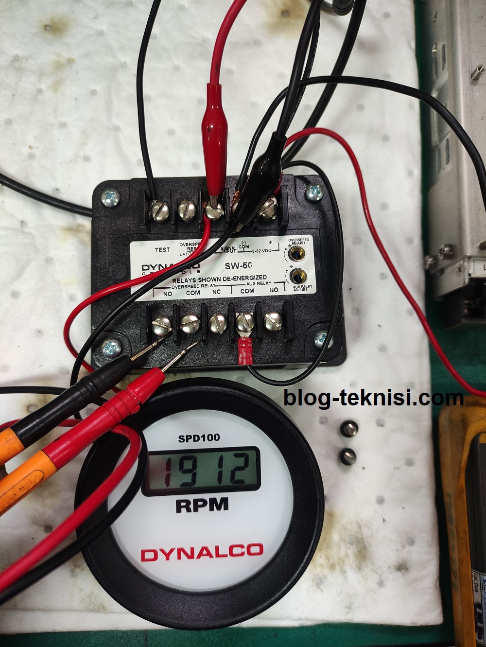
| Figure 1.2 - Engine Overspeed Test |
#Verify Current Calibration:
#Change the Setpoints:
Blog.Teknisi
1). Connect a signal generator to the SW-50
magnetic pickup input (Signal Input).
2). Set the signal generator to a low frequency. Slowly increase the frequency.
Using an ohmmeter across each relay contact, in turn, determine the frequency
at which the relays change state (Note: Overspeed Relay will latch if terminal 4
is not grounded).
 |
| Figure 1.3 - Verify Overspeed (Test) |
1). Remove the screws in the access holes for the relay adjustment trim pots.
2). Set the signal generator to the frequency at which the relay should change
state.
3). Using a small/ flat screwdriver, adjust the trim pot for the appropriate relay until
the relay changes state.
 |
| Figure 1.4 - Adjust the trim pot |
4). Decrease the frequency, and then slowly increase it to verify that the relay trips
at the appropriate point.
Read More:
Pgslot แหล่งรวมสล็อตสุดฮิต โบนัสแตกง่าย 100 % แจก free เครดิต PG เพียงแค่สมัครสมาชิก สามารถเข้าเล่นได้ตลอด 24 ชั่วโมง เล่นง่าย ได้เงินจริง ฝากถอนด้วยระบบออโต้
ReplyDeleteQuality Testing Lab for Reliability & Traceability
ReplyDelete