Allison 3000/4000 Product Families - Electronic Controls
Electronic Controls - Fleet


A). Transmission Control Module - TCM


Allison Electronic Controls work with the hydraulic system
to control and continually refine shifts.
- Allison 5th Generation Controls represent the most current
control version used with 1000/2000/3000/4000 Product Families Transmissions.

- Previous 3000/4000 Electronic Controls versions include WTEC II,
WTEC III, and 4th Generation Controls.

- 5th Generation Controls shares operating theory and similar
componentry with previous control system versions.
- Each control system version has its own Troubleshooting Manual, recognize which control system the Transmission utilizes and reference the
appropriate manual when diagnosing and making repairs.

- This training is based on the most current version of 5th Generation Controls in production at the time of development.
The Transmission Control Module (TCM) is an onboard
computer connected to other Electronic Control components (and the vehicle, by wiring harnesses).
- The wiring harnesses offer J1939 and diagnostic tool interface, and
enable connection to other vehicle systems using analog wires.

- The TCM electrically controls solenoids located in the control valve
body to determine when and how shifts occur.

- Key factors affecting shift control include Engine speed, Transmission turbine speed, Transmission output shaft speed, and the amount of throttle being requested (throttle position).
- Based on these and other inputs, the TCM energizes and de-energizes
solenoids.

- Solenoids direct fluid flow throughout the Transmission to position
valves, apply clutches, and provide cooling and lubrication.

The TCM is a microcomputer which monitors all aspects of
the Electronic Control system and, among other critical tasks, commands and
controls automatic shifts.
- The TCM is externally mounted in the vehicle cab or on the chassis.

- TCMs are manufactured in 12-volt and 12/24-volt models.

- Markings on the TCM include the programmed calibration, Allison part
number and TCM serial number.

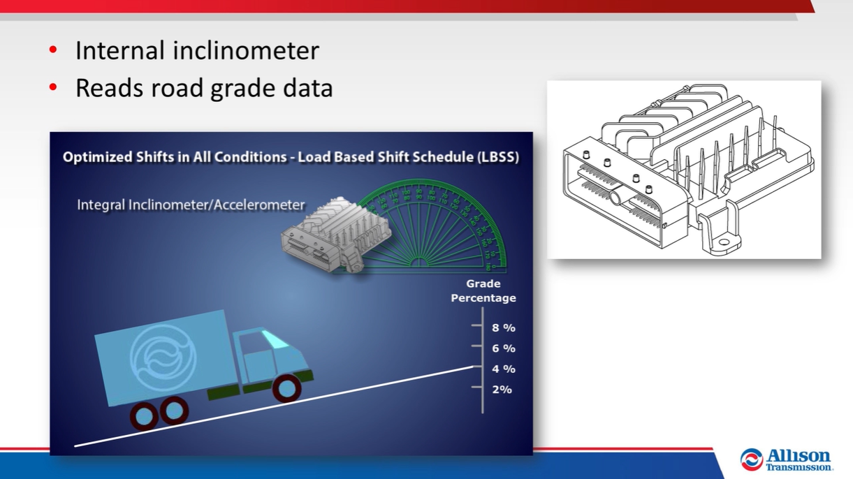
- TCMs include an integral inclinometer to include road grade data as
part of the shift control and optimization processes.
TCMs utilize two levels of software – base programming and
calibration.
- Base programming is the term describing basic operational features
included with the TCM to perform general tasks.
- Calibration is the term used to describe features which can be
utilized for specific vehicle or vocational equipment functions.

B). Throttle Position Signal (TPS)
The TCM monitors the amount of throttle being requested
when determining range selection and shift timing.
- Throttle position is most commonly communicated to the TCM on the
J1939 datalink.

- But Allison does make available an analog Throttle Position Sensor
(TPS).
- The analog TPS can be mounted to the Engine, Chassis or Transmission
and sends signals to the TCM through a wiring harness.

- The analog TPS contains a pull actuation cable and potentiometer, one end of the cable is attached to the Engine fuel lever and the other is
attached to the potentiometer inside the TPS housing.

- Output voltage from the TPS indicates throttle position which helps
the TCM determine shift timing.

- The analog TPS must be correctly installed and adjusted for proper Transmission operation.

C). Speed Sensors
Three sensors provide speed information to the TCM – the
input (Engine) speed sensor, turbine speed sensor, and output speed sensor.

- All three sensors utilize variable reluctance design.

- The input speed sensor is externally located on the Transmission
torque converter housing.

- 4000 Product Family turbine speed sensors are externally located on
the main housing, 3000 Product Family turbine speed sensors are internally
located in the control valve module.

- The output speed sensor is externally located on the rear cover or
retarder housing, except for 3000 7-speed models, which has the output
speed sensor internally located in the transfer case housing.

- The input speed signal is generated by sensing external ribs on the
shell of the torque converter pump.

- The turbine speed signal is generated by sensing the splines on the
rotating clutch drum.

- The output speed signal on non-retarder, non-drop-box 3000 Transmissions
is generated by sensing movement of a tone wheel located on the P3 carrier.

- The output speed signal on retarder-equipped 3000 Transmissions is
generated by sensing movement of the retarder rotor.

- The output speed signal on drop-box equipped 3000 Transmissions is
generated by sensing movement of the transfer case idler gear.

- The output speed signal on all 4000 Transmissions is generated by
sensing movement of the output bearing retention nut.

Comparing turbine and output speeds allows the TCM to determine
if the appropriate Transmission range is attained based on operator input and
operating conditions.
- Speed sensor information is also used to control the timing of
clutch apply pressures, resulting in smooth, controlled shifts.
- Some diagnostic tests compare actual speed sensor information to
profiles stored in the TCM memory, DTCs can result if variances exist
between actual and stored profile data.

- Speed sensor data is also used by the TCM’s "adaptive" feature which
continually monitors and refines shift quality.
D). Solenoids and Control Valve Module
5th Generation Controls include solenoids which direct
fluid pressure and flow within the Transmission.
- Solenoids are located in the hydraulic control valve module.

- The control valve module contains a main body assembly and a solenoid
valve body assembly, both are mounted to an aluminum channel plate.

- The TCM electrically commands the solenoids to control fluid flow to
the clutches.

E). Shift Selectors
Allison 5th Generation Controls shift selectors are
electronic, remote-mounted from the TCM, and communicate with the TCM via the
CAN1 or CAN2 SAE J1939 communications datalink.

- A variety of selector configurations are available for different
vocational applications and operational needs.

- Along with providing operator range selection signals, the shift
selector can also be used to access the control system diagnostic and Oil
Level Sensor modes.

- In addition to the J1939 interface, an analog direction signal wire
is connected to the shift selector to enable limited operation in the
event of a J1939 communication failure.

Some key shift selector display patterns include:
- Select side flashing – indicates a requested shift is being
inhibited.

- Select side blank – indicates the presence of an active DTC,
typically accompanied by the Monitor side displaying the range in which
the Transmission is locked.

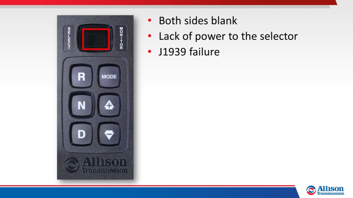
- Both sides blank – indicates a lack of power to the selector or a
J1939 failure.
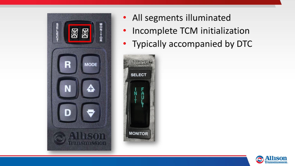
- All segments illuminated on both sides for more than 12 seconds –
the TCM has not completed initialization, typically accompanied by a DTC (depending on calibration), a text message may also be displayed.
- Double cat-eyes – indicates a J1939 failure which is always
accompanied by a DTC.

Depending on TCM programming, the selector Mode button may
be used to change Transmission shift characteristics or activate programmed
features.
- For example, the Mode button may be programmed so that the operator
can choose between Economy or Performance shift schedules.
- Another example – the Mode button may be programmed to enable the
vehicle’s PTO system.
- The Mode button is also used to navigate display messages when in
the OLS, prognostics or diagnostic modes.

F). Wiring Harnesses
Electronic control components are connected using external
and internal wiring harnesses.
- Harness configurations can vary depending on the installation and
vehicle type.
- An external harness connects the TCM, internal Transmission
components and external vehicle system components.

- The internal harness is located inside the control valve module and
provides connections between the TCM and solenoids, pressure switches and
sensors.

Vehicle Interface describes the connections between vehicle
systems and the Transmission electronic control system.
- Mandatory interface connections (for example, power and ground) are
required for basic Transmission operation.

- Optional Input and Output functions are programmed features which
can control specific equipment and Transmission operation depending on
detected conditions or operator commands, Allison Tech Data (available on
the Allison Hub) provides detailed Package and Group information as well
as Input/Output function descriptions and interface wiring schematics.

- Technicians need to be aware of programmed Input/Output functions
which may impact how the Transmission or equipment operate, what may seem
like an operational issue may actually be an active Input/Output function
performing as designed.

A vehicle interface module (VIM) is available from Allison
for simplifying mandatory system connections, including power, ground and ignition
signal.
- The VIM contains relays, fuses, and connection points which can be
used to simplify mandatory interface and connections for input/output
features not interfaced on the J1939 datalink.
- VIMs are available for both 12-volt and 24-volt systems.

The Troubleshooting Manuals include harness connector
repair procedures.

G). Shift Inhibits
Some “built-in” shift inhibits are included with the TCM
programming and logic.
- Engine Speed Inhibit prevents an attempt to shift from Neutral to
any moving range if the Engine speed is above idle (900 rpm for
non-emergency vehicles and 1260 rpm for emergency vehicles).
- Direction Change Inhibit prevents a direction change from Drive to
Reverse or from Reverse to Drive if output speed or throttle percent are
above pre-determined limits.
- Auxiliary Function Range Inhibit is an Input/Output feature that can
prevent shifts out of Neutral when auxiliary equipment is in operation.
- The Select side of the shift selector display flashes when shift
inhibits are active.

Allison DOC® includes a Shift Inhibits grid that indicates
status of any shift inhibits.
- Allison DOC® also has the ability to run a report showing currently
active shift inhibits and any shift inhibits that may have been active
since the last time DTCs were cleared.

Blog.Teknisi
0 Response to "Allison 3000/4000 Product Families - Electronic Controls"
Post a Comment