Harness for Engine's Display (Caterpillar, Cummins, and Detroit Engines)
Engine's Display
 |
| Figure 1.1 - Engine's Display |
1). CAT Messenger Display (Caterpillar Engines)
CAT P/N: #2395025-12 (Display Module Group). Read More: How to Setting the New CAT Messenger Display?
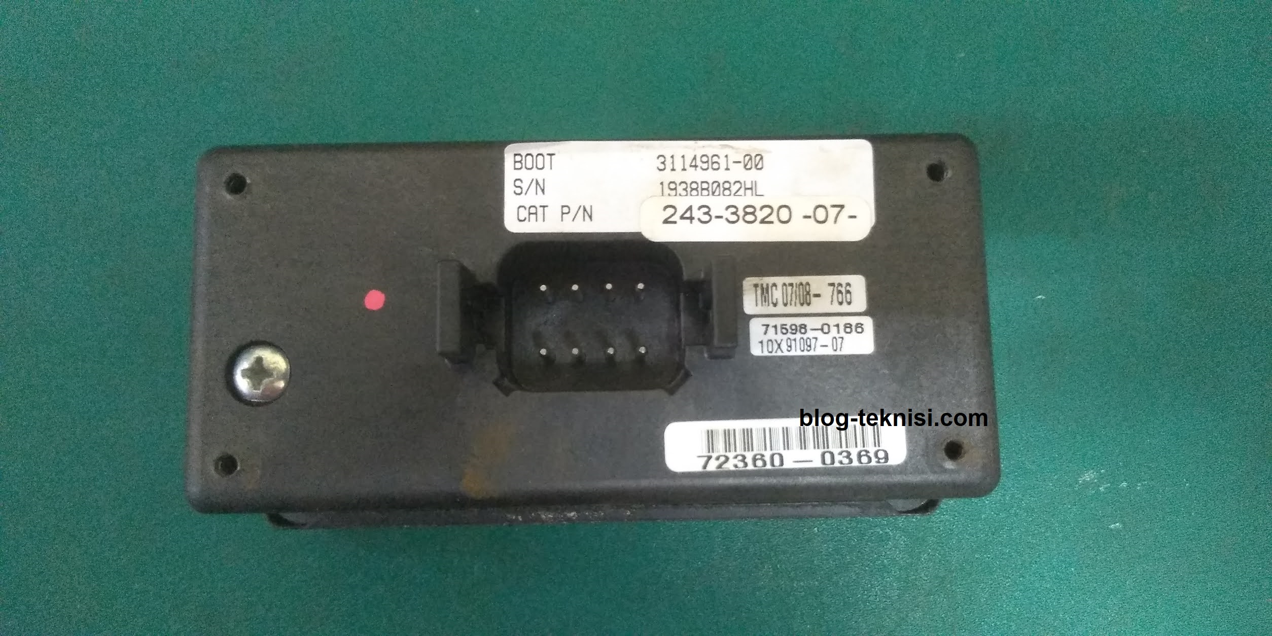 |
| Figure 1.2 - Back View (CAT Messenger Display) |
#Connector
Un-switched Battery (+) ↔ Pin 1 ↔ Red
Battery (-) ↔ Pin 2 ↔ Black
Battery Switched (+) ↔ Pin 3 ↔ Red
Dimmer ↔ Pin 4 ↔ Purple
ATA (-) ↔ Pin 5 ↔ Blue
ATA (+) ↔ Pin 6 ↔ Yellow
J1939/ CAN (+) ↔ Pin 7 ↔ Yellow
J1939/ CAN (-) ↔ Pin 8 ↔ Green
NOTE: Installation and Operation of the CAT Messenger Driver Information Display (REHS1413-05), download here.J1939/ CAN (-) ↔ Pin 8 ↔ Green
2). Murphy PowerView PV-101 (Caterpillar, Cummins, and Detroit Engines)
FW Murphy P/N: 78-70-0244 (PV101-A)
 |
| Figure 1.3 - Back View (Murphy PowerView) |
#Connector
Battery (+) ↔ Pin 1 ↔ Red
J1939/ CAN (+) ↔ Pin 2 ↔ Yellow (Pin 2-3 installed with 120 ohms resistors)
J1939/ CAN (-) ↔ Pin 3 ↔ Green
J1939 (-)/ Shield ↔ Pin 4 ↔ Black
Dimmer ↔ Pin 5 ↔ Black
Battery (-) ↔ Pin 6 ↔ Black
NOTE: PowerView - Wiring Diagrams, download here.
3). Electronic Display Module/ EDM (Detroit Engines)
DDC P/N: 23517174 (EDM C&I)
 |
| Figure 1.4 - Back View (EDM) |
#Connector
A ↔ Battery (+) ↔ wire jumper to connector C (Diagnostic Port) ↔ Red
B ↔ Battery (-) ↔ wire jumper to connector E (Diagnostic Port) ↔ Black
C ↔ J1708/ J1587 Hi (+) ↔ wire jumper to connector A (Diagnostic Port) ↔ Green/ Yellow
D ↔ J1708/ J1587 Lo (-) ↔ wire jumper to connector B (Diagnostic Port) ↔ Green
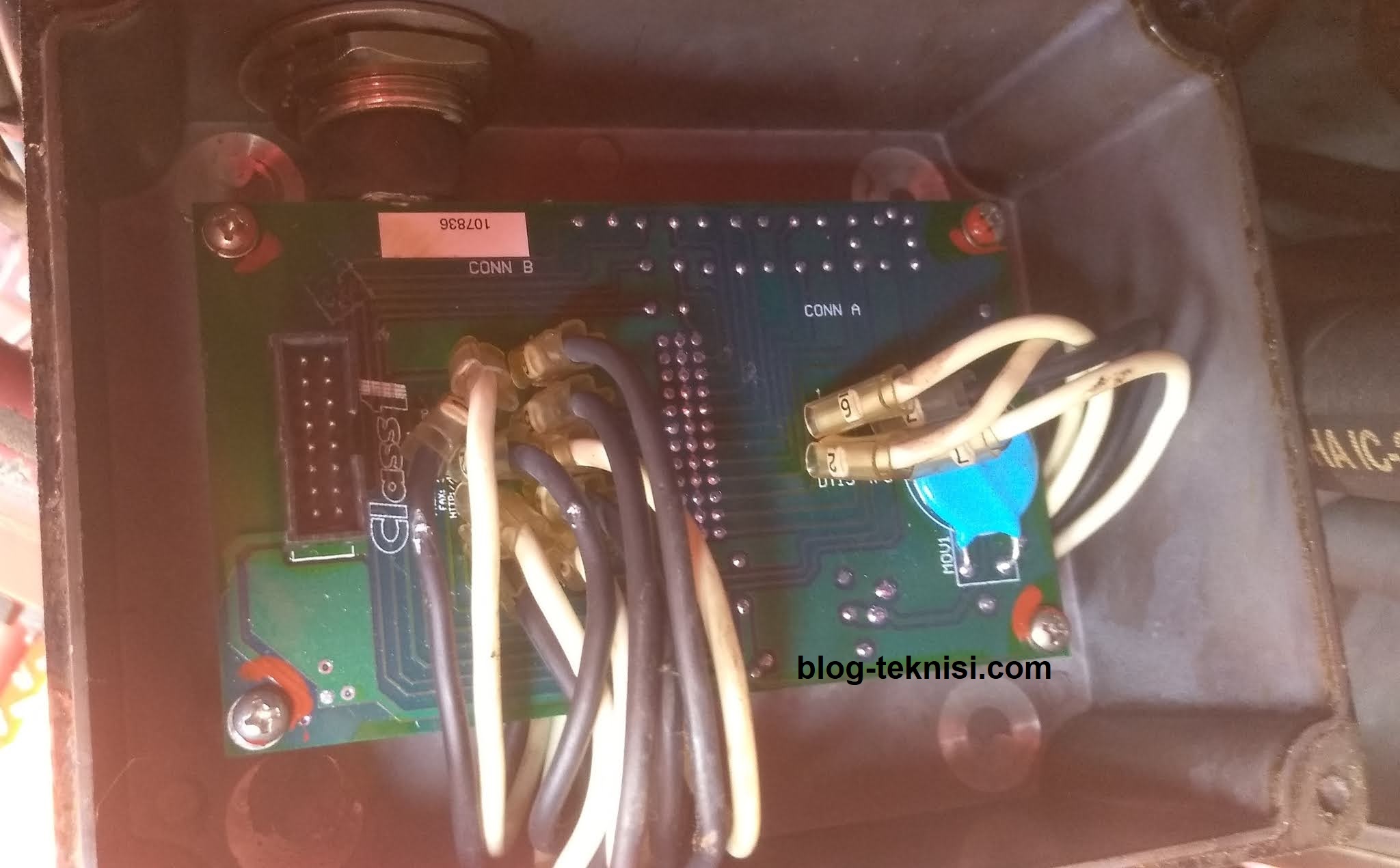
4). Electronic Engine Commander/ EEC (Detroit Engines)
 |
| Figure 1.5 - Front View (DD EEC) |
A-1 ↔ DDEC Ignition Power ↔ DDC#439 ↔ Switched Battery (+) ↔ Pink
A-2 ↔ DDEC Accessory Ground ↔ DDC#953 ↔ Battery (-) ↔ Black/ White
A-3 ↔ DDEC Data Link (+) ↔ DDC#900 ↔ J1708/ J1587 Serial Link ↔ Green/ Yellow
A-4 ↔ DDEC Data Link (-) ↔ DDC#901 ↔ J1708/ J1587 Serial Link ↔ Green
 | |
|
#CONN B
B-1 ↔ DDEC PGS Mode Select ↔ DDC#523 ↔ Output (Ground) to DDEC ↔ Gray/ Red ↔ SIGNALS DDEC TO TOGGLE BETWEEN PRESSURE AND RPM MODE.
B-2 ↔ OEM Interlock POS Input ↔ Input (+12 VDC) from OEM PARKING BRAKE/NEUTRAL (THROTTLE READY LED).
B-3 ↔ Cavity Plug ↔ No Connection.
B-4 ↔ DDEC PSG-PSI Mode Active ↔ DDC#499 ↔ Input (Ground) from DDEC ↔ Blue ↔ GROUND FROM DDEC WHEN PSG PRESSURE MODE IS ACTIVE (PRESSURE LED LIGHTS).
B-5 ↔ DDEC PSG Enable ↔ DDC#543 ↔ Output (Ground) to DDEC ↔ Orange/ Black ↔ GROUND TO DDEC TO TURN CRUISE CONTROL (PSG) ON (CRUISE ON/OFF CONTROL).
B-6 ↔ DDEC PSG Increase ↔ DDC#545 ↔ Output (Ground) to DDEC ↔ Blue/ Yellow ↔ GROUND TO DDEC TO INCREASE RPM/PRESSURE (RESUME/ACCEL INCREASE).
B-7 ↔ DDEC PSG Decrease ↔ DDC#541 ↔ Output (Ground) to DDEC ↔ Yellow/ Red ↔ GROUND TO DDEC TO DECREASE RPM/PRESSURE (SET/COAST DECREASE).
B-8 ↔ DDEC Cruise Active ↔ Input (Ground) from DDEC GROUND FROM DDEC TO EEC WHEN CRUISE CONTROL (PSG) SYSTEM IS ACTIVE.
B-9 ↔ ALARM ↔ Output (Ground) to Alarm.
B-10 ↔ OK to PUMP Interlock POS Input ↔ Input (+12 VDC) from OEM PTO ENGAGED/PUMP ENGAGED.
B-11 ↔ Cavity Plug ↔ No Connection.
B-12 ↔ Low Fuel ↔ Input (ground) from OEM.
DDC circuit numbers and port assignments shown are typical but can differ from application to application. Read More: Operating the Detroit Diesel Electronic Engine Commander (EEC).
Blog.Teknisi
0 Response to "Harness for Engine's Display (Caterpillar, Cummins, and Detroit Engines)"
Post a Comment