Allison 3000/4000 Product Families - Preventive Maintenance
Allison 3000/4000 Fleets Training

- Current Allison On-Highway Transmissions are equipped with
prognostics which indicate when service is due.
- Allison service publications, including the Service Manuals and the
latest revision of Service Information Letter 10-TR-99, provide procedures
and information regarding service intervals, approved fluids, refill
capacities, and more.

- Inspect Transmission seal and gasket areas for leaks, including the
input and output seals, the Transmission control valve module gasket, and
the gaskets sealing the converter housing and rear cover to the main Transmission housing.

- Ensure the Transmission breather is unobstructed, undamaged, and not
leaking. Any more than slight seepage at the breather indicates a
potential issue.

- Check components and hardware securing the Transmission to the Engine and vehicle for proper installation and damage.

- Verify cooler lines are properly routed and secured. Check for
leaking lines, hoses and fittings.

- Visually inspect the electrical harnesses and connectors for proper routing and secure installation.


- Check U-joints for wear, damage, and proper lubrication.
- Check carrier and support bearings for wear and damage.
- Inspect the driveshaft sections for damage, dents and missing
weights.
- Verify all hardware is properly installed and undamaged.


- With the Transmission at normal operating temperature (160 to 199
degrees Fahrenheit, or 71 to 93 degrees Celsius), remove the plug and
allow the fluid to drain.
- The end of the drain plug is magnetic. Some metallic particles on
the magnet are normal, but excessive or large pieces of metal may indicate
a transmission issue.
- Clean the magnet, replace the drain plug O-ring, allow the fluid to
completely drain, then install and torque the plug to specification.

- Inspect the drained fluid for discoloration and debris.
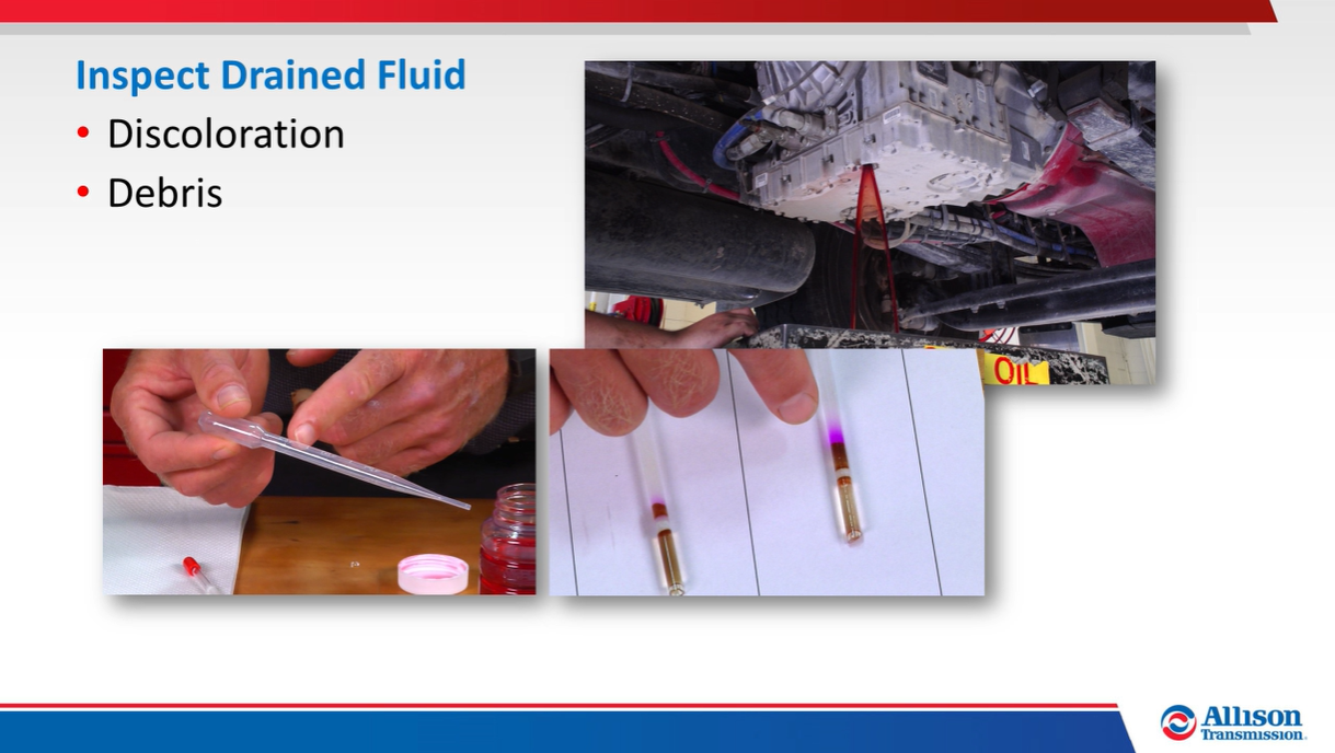
- Discolored fluid can indicate water or coolant contamination; if
contamination is suspected, check the fluid using the GlyTek Test kit or a
similar Allison-recommended process.
- Reference Technician’s Guide GN2055, "Automatic Transmission Fluid Understanding/Analysis" for additional technical details.

- Remove the filter cover bolts.

- If necessary, a screwdriver can be inserted into a cast relief to
loosen the cover. Leave a couple of cover bolts loosely installed to
prevent the cover from dropping out of the control valve module.
- The filters and covers are removed from their bores as an assembly.
- Pull the filters from the covers, remove the cover seal rings, and
remove the cover gasket.

- Clean the covers and the control valve module where the covers seat
– remove all old gasket material.

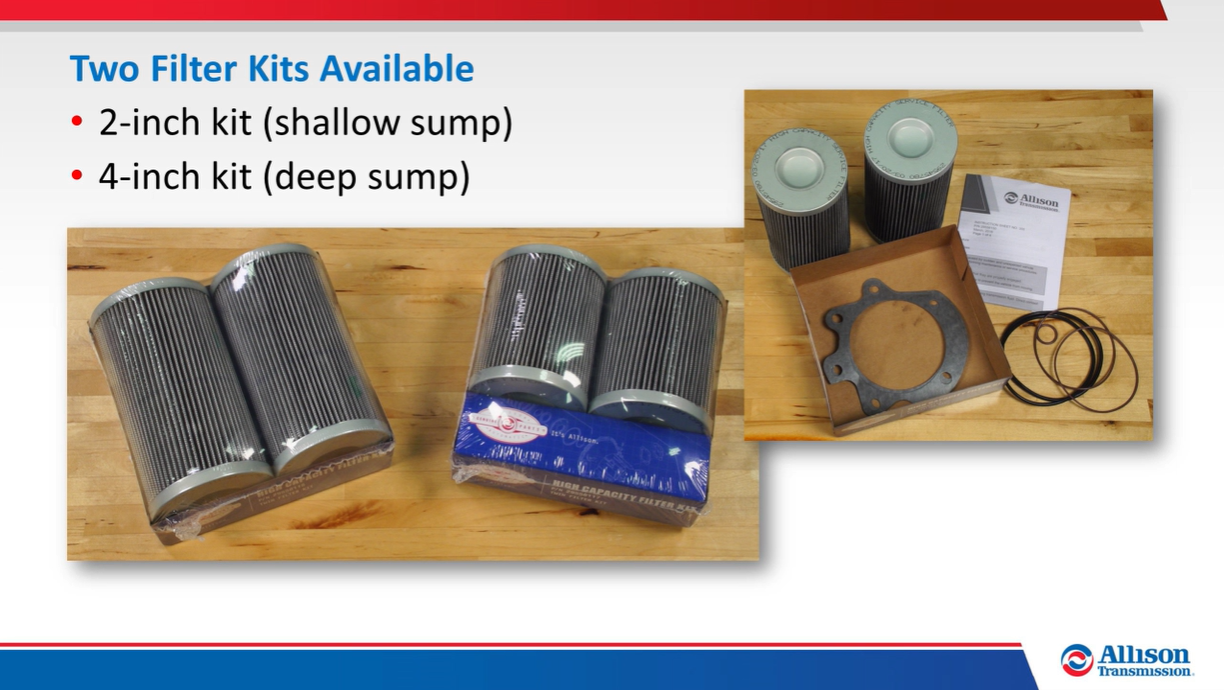
- Two filter kits are available, depending on the control valve module
depth – as a general rule of thumb, control valve modules measuring
approximately two and one-half inches or less in height use the two-inch
filter kit. Control valve modules measuring over two and one-half inches
use the four-inch filter kit.
- Install the new cover seal rings, lightly lubricate the internal
filter O-ring, then assemble each filter to its cover – the filters and
covers are identical and can be mixed.

- Lightly lubricate the cover seal rings, then install a new gasket on each cover.

- Insert the assemblies into the bores, then install and torque the cover bolts.

Reference Allison Technical Publications for transmission
fluid recommendations and initial refill capacities.
- Service Information Letter 10-TR-99 is continually revised to
include the most current information.
- The Allison Transmission website maintains an
Approved Fluids list.


- A Cold Check is performed to determine if the Transmission has enough fluid to be operated safely until a Hot Check can be made.

- Both checks are performed with the vehicle parked, parking brake
applied, the Transmission in Neutral, and the Engine at idle.

- Run the Engine for at least one minute, then with the service
brakes applied, shift the Transmission to Drive, Neutral, Reverse, then
back to Neutral.

- Keep the Engine running, remove the Transmission dipstick, wipe it
clean, then reinstall the dipstick in the fill tube.

- Remove the dipstick and check the level – repeat the procedure to
verify the reading.
- When the fluid in the Transmission sump is below normal operating
temperature (160 to 199 degrees Fahrenheit, or 71 to 93 degrees Celsius),
the fluid level should be within the Cold Run band on the dipstick.
- When the fluid in the Transmission sump is at normal operating
temperature, the fluid level should be within the Hot Run band on the
dipstick.
Add or drain fluid as needed, and take a moment to verify there are no Transmission fluid leaks at the filter or drain plug.


The OLS becomes
accessible when the fluid temperature is above 104 degrees Fahrenheit (40
degrees Celsius) and below 220 degrees Fahrenheit (104 degrees Celsius).
- The vehicle
must be stationary, on a level surface, with the Transmission in Neutral
for approximately 2 minutes to allow the fluid to settle.

- Leave the Engine idling with the vehicle parking brake applied.
- On pushbutton
selectors, press the Up and Down arrow buttons simultaneously one time.

- On lever
selectors, press the Display Mode/Diagnostics button one time.

The system can
immediately access the Oil Level Mode, or it may enter a countdown while
various conditions are automatically monitored.
- Once accessed,
the feature indicates the Transmission fluid level is OK, or that the
level is high or low by a specified number of quarts.
- The system may
also display a variety of messages, including indications that Engine
speed may be too high or that fluid temperature is not within the
acceptable range.

Exit the OLS mode on
pushbutton selectors by pressing the Neutral button.

Exit the OLS mode on
lever selectors by pressing the Display Mode/Diagnostics button until the Range
Selected/Range Attained display appears. The number of required button pushes
varies depending on the Transmission system configuration.


- When prognostics are enabled for the Transmission, the Trans Service
icon (wrench) in the digital display indicates Oil Life and Filter Life
status.
- If the indicator illuminates or stays on for 2 minutes after the Engine is started and Drive is selected, a fluid change is needed.
- If the indicator flashes on and off for 2 minutes after Drive is
selected, a filter change is needed.
- Once a prognostics warning becomes active and the Trans Service icon
is illuminated, a Diagnostic Trouble Code (DTC) sets and the Check
Transmission light illuminates if fluid or filter service is not performed
within a specified period of time.


- If the Transmission does not include an Oil Level Sensor, press the
buttons just once.
- The remaining oil life is displayed as a percentage between 0 and
100.
- Exit the fluid life display on pushbutton selectors by selecting
Neutral. On lever selectors, move the lever to any range position.
After servicing the Transmission, the system calibration
may allow the Oil Life Monitor to be reset using the shift selector.

- While in the Oil Life Monitor display mode, press and hold the Mode
button for 10 seconds.
- Or, with the Engine OFF and ignition ON, shift between
N-D-N-D-N-R-N, pausing no more than 3 seconds between consecutive shifts.
- The Trans Service icon illuminates briefly following a reset to
indicate the reset was successful
- If the reset cannot be performed using the shift selector,
Allison DOC® may be required to reset the Oil Life Monitor.


- If the Transmission does not include an Oil Level Sensor, press the
buttons just twice.
- The display indicates whether the filters are OK or in need of
replacement.
- Exit the filter life display on pushbutton selectors by selecting
Neutral. On lever selectors, move the lever to any range position.

On 3000/4000 Product Family Transmissions, the Filter Life
Monitor automatically resets after the filters are serviced, with no additional
actions required by the servicing Technician.

- With the Engine OFF and ignition ON, perform the following shift
sequence: N-R-N-D-N-R-N-D-N-R-N-D-N.
- The Trans Service indicator flashes if TES 389 is the current
setting and illuminates solidly if TES 295 is the current setting.
To change the Transmission fluid type, wait 5 seconds after
entering the Transmission fluid type feature and perform one of the following
sequences:

- To select TES 295, shift N-R-N. The Trans Service indicator
illuminates solidly to indicate TES 295 has been selected.
- To select TES 389, shift N-D-N. The Trans Service indicator flashes
to indicate TES 389 has been selected.
- The system automatically exits the fluid type selection feature
after 30 seconds, the feature can also be exit by turning the ignition OFF.

- Only one Transmission fluid type selection may be made after
entering the selection feature, all other attempts will be ignored until
the feature is exited and re-entered.
- The Transmission fluid selected must match what is actually in the Transmission or the Oil Life Monitor notifications will be inaccurate,
causing pre-mature TES 295 fluid changes, or possibly resulting in Transmission damage from running a TES 389 fluid too long.

- Transmission fluid cools, lubricates and transmits hydraulic power.
- A low fluid level can cause overheating, a lack of lubrication, and
can starve the Torque Converter and Clutches.
- A high fluid level can cause aerated fluid, resulting in erratic
shifting, overheating, and fluid being expelled through the breather or
the dipstick fill tube.
Allison Technical Publications provide specifications which
can be referenced to verify the fill tube is properly designed, that the
dipstick is the correct length, and that the dipstick is appropriately marked.
- Verify the dipstick calibration if the Transmission refill seems to
require excessively more or less fluid than anticipated.

- Verify the dipstick calibration if excessive fluid has been expelled
at the breather or through the fill tube even though the level appears to
be correct.

0 Response to "Allison 3000/4000 Product Families - Preventive Maintenance"
Post a Comment